What is it
Carrier aggregation is a technique implemented in LTE-Advanced to increase available bandwidth, which directly increases the overall bitrate for the user. To ensure that older devices can still operate on the network, CA is designed to maintain backward compatibility with Release 8 (R8) and Release 9 (R9) User Equipment (UE) by aggregating standard R8/R9 carriers.
Here are the foundational rules and capabilities of CA:
- Duplex Modes: It can be utilized in both Frequency Division Duplexing (FDD) and Time Division Duplexing (TDD) deployments.
- Component Carriers (CC): Each individual carrier that is aggregated is called a component carrier, or CC.
- Bandwidth Limits: A system can aggregate a maximum of five CCs, capping the total maximum bandwidth at 100 MHz.
- Individual CC Bandwidths: A single CC can have a bandwidth of 1.4, 3, 5, 10, 15, or 20 MHz. The aggregated CCs are not required to be the same size; they can have different bandwidths.
- Uplink vs. Downlink: An LTE-Advanced UE can be allocated resources on two or more CCs for both downlink (DL) and uplink (UL). However, the number of UL component carriers must always be equal to or less than the number of DL component carriers.
- TDD Specifics: For TDD systems, the number of CCs and their individual bandwidths will typically be identical for both DL and UL.
Note
Becasue TDD shares the same carrier (frequency channel) for both DL and UL, aggregate happens on both directions.
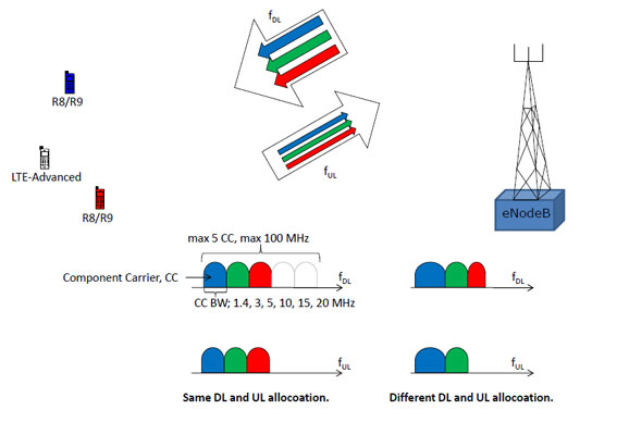 A visual example of CA using FDD. It illustrates that an LTE-Advanced UE can utilize DL and UL resources across an aggregated block of multiple CCs. In contrast, older R8/R9 UEs are restricted to being allocated resources on just ONE of those component carriers.
Types of Carrier Aggregation
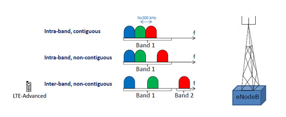
Operators have different frequency allocations, so aggregating carriers perfectly isn’t always possible. The document outlines three distinct ways CCs can be arranged, which are visually depicted in Figure 2:
- Intra-band, contiguous: This is the most straightforward arrangement, where CCs are placed right next to each other within the same operating frequency band. The spacing between the center frequencies of two adjacent CCs must be a multiple of 300 kHz (Nx300 kHz, where N is an integer).
- Intra-band, non-contiguous: The component carriers belong to the same frequency band but are separated by one or more frequency gaps.
- Inter-band, non-contiguous: The component carriers belong to entirely different operating frequency bands.
Configurations and Bandwidth Classes
To practically implement CA, 3GPP initially specified a limited number of combinations based on operating bands and the number of CCs. This is defined using a few specific metrics:
- Aggregated Transmission Bandwidth Configuration (ATBC): This represents the total number of aggregated physical resource blocks (PRB).
- CA Bandwidth Class: This metric defines a specific combination of the maximum ATBC and the maximum number of CCs. Releases 10 and 11 define three specific bandwidth classes:
- Class A: Maximum ATBC ⇐ 100, maximum 1 CC.
- Class B: Maximum ATBC ⇐ 100, maximum 2 CCs.
- Class C: 100 < ATBC ⇐ 200, maximum 2 CCs.
Understanding CA Configurations A CA Configuration indicates the exact operating band(s) and bandwidth class(es) being used.
- Example 1:
CA_1Cdictates an intra-band contiguous arrangement on operating band 1 using bandwidth class C. - Example 2:
CA_1A-5Bindicates inter-band CA, utilizing band 1 with bandwidth class A, and band 5 with bandwidth class B.
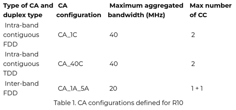
Table 1 (Release 10) vs. Table 2 (Release 11):
- Release 10 (Table 1): Defined only three CA configurations: CA_1C (intra-band contiguous FDD), CA_40C (intra-band contiguous TDD), and CA_1A_5A (inter-band FDD).
- Release 11 (Table 2): Introduced a large number of additional configurations. Even with these additions, the maximum aggregated bandwidth remained 40 MHz with a maximum of 2 CCs.
- Uplink Restrictions in R10/R11: For both releases, any Uplink CC must have the exact same bandwidth as its corresponding Downlink CC. Furthermore, for inter-band CA configurations, there is only ONE Uplink CC (meaning no Uplink Carrier Aggregation is used). Uplink inter-band CA configurations are slated for introduction in Release 12.
Primary and Secondary Serving Cells
When CA is active, the UE is connected to a number of serving cells, with exactly one serving cell for every component carrier (they basically the same).
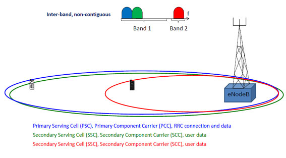
Because CCs can operate on different frequency bands (inter-band), they experience different levels of pathloss, meaning the physical coverage area of these serving cells can vary significantly. Higher frequencies experience greater pathloss. Figure 3 illustrates this by showing two UEs: the black UE is within range of all three component carriers, while the white UE is too far to fall within the coverage area of the red component carrier. Networks can deliberately plan different CCs to provide different cell sizes.
The cells are divided into two categories:
- Primary Serving Cell (PSC): Served by the Primary Component Carrier (PCC) for both DL and UL, this single cell handles the entire RRC connection. The UE receives Non-Access Stratum (NAS) information, like security parameters, exclusively on the DL PCC. The DL PCC is also where the UE listens to system information while in idle mode. The UL PCC is strictly used to send the PUCCH.
- Secondary Serving Cells (SSC): All other aggregated carriers are Secondary Component Carriers (SCC DL and UL), which serve the Secondary Serving Cells. These are used for transmitting user data.
It is also important to note that two different UEs utilizing the exact same set of CCs can be assigned different Primary Component Carriers.