1. The Basics of Traffic: Duplexing (FDD vs. TDD)
Before we look at the frame structure itself, we must understand how the network handles two-way conversation (sending and receiving). In LTE, this is called Duplexing. There are two main ways to do this, similar to how traffic flows on a road.
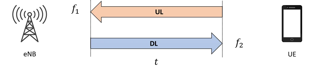
FDD (Frequency Division Duplexing) Imagine a highway with a physical barrier in the middle. Cars can drive North and South at the same time without hitting each other because they are in different “lanes.”
- How it works: Communication happens on two different frequency bands. One frequency is strictly for uploading (UL), and the other is strictly for downloading (DL).
- Key Feature: Because the frequencies are separate, the phone (UE) and the tower (eNB) can transmit and receive at the exact same time.
 TDD (Time Division Duplexing)
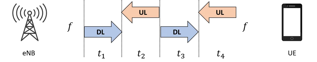
Now, imagine a narrow bridge where only one car can pass at a time. A traffic light controls the flow: “Traffic flows North for 1 minute, then South for 1 minute.”
TDD (Time Division Duplexing)
Now, imagine a narrow bridge where only one car can pass at a time. A traffic light controls the flow: “Traffic flows North for 1 minute, then South for 1 minute.” - How it works: Communication happens on just one frequency band.
- Key Feature: You cannot upload and download simultaneously. You must take turns. The system rapidly switches between transmission and reception times.
2. The Architecture of Time: Frame Structure
LTE is incredibly precise. It organizes time into tiny containers to ensure data is synchronized. This organization is called the Frame Structure.
The Hierarchy of Time Think of this like a clock, but much faster.
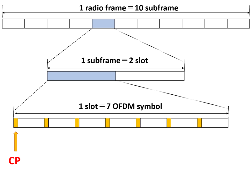
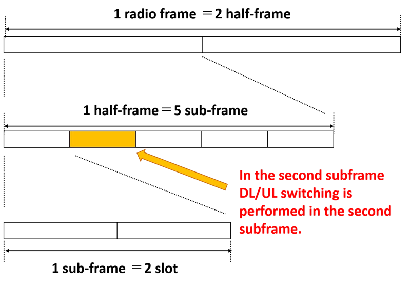
- Radio Frame: This is the largest container. It lasts for 10 milliseconds (ms).
- Subframe: The Radio Frame is sliced into 10 smaller pieces called Subframes. Each subframe lasts 1 ms.
- Slot: Each Subframe is further divided into two Slots. Each slot lasts 0.5 ms. Since 1 Subframe = 2 Slorightts, a full Radio Frame (10 subframes) contains 20 Slots.
- Symbol: This is the smallest unit that actually carries the data. One Slot contains seven OFDM symbols.
3. Solving the Echo Problem: The Cyclic Prefix (CP)
When radio waves travel from a tower to your phone, they don’t move in a perfect straight line. They bounce off buildings, mountains, and trees. This creates Multipath—meaning the same signal arrives at your phone at slightly different times (like an echo).
If these “echoes” arrive while the next symbol is starting, they act as noise and ruin the data. This is called interference.
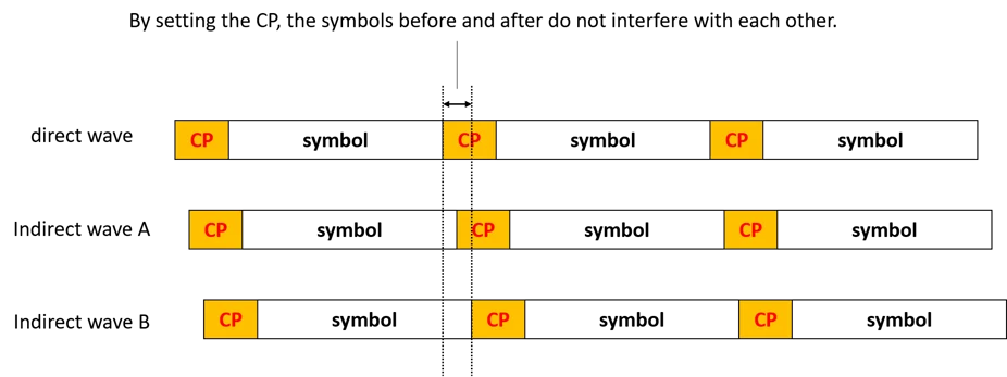
The Solution: Cyclic Prefix (CP) To fix this, LTE inserts a small “gap” or buffer at the beginning of every symbol.
- What it does: It copies a tiny slice of the end of the symbol and pastes it at the front.
- Why it helps: This buffer absorbs the “echoes” (delayed waves) so they don’t crash into the next symbol. It ensures that the symbols before and after do not interfere with each other.
Note
The receiver’s antenna sees a mixture (a sum) of all three. You cannot physically stop Wave A or B from arriving. They are real radio waves bouncing off buildings.
4. TDD Specifics: The “Special Subframe”
If you are using FDD (two frequencies), the structure is simple (Type 1) because you just send data continuously.
However, if you are using TDD (one frequency), you have a problem: How do you switch from Downloading to Uploading without crashing? You cannot switch instantly; you need a tiny pause to turn the radio from “Receive mode” to “Transmit mode.”
This is handled by Frame Structure Type 2, which introduces the Special Subframe (SS).
In TDD (Type 2), we add a new layer to the time hierarchy that does not exist in FDD.
- Radio Frame (10ms): The standard container.
- Half-Frame (5ms): This is unique to TDD. The 10ms frame is split perfectly into two 5ms halves. Why? Because many TDD configurations repeat themselves every 5ms. This allows the network to switch directions frequently, keeping latency low.
- Subframe (1ms): Each Half-Frame contains 5 Subframes (Total 10 per frame).
- Slot (0.5ms): As usual, each subframe holds 2 slots.
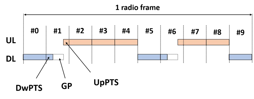
The Golden Rule of TDD Anchors: Regardless of how you configure the frame, three things are immutable (never change) to ensure the phone can always find the tower:
- Subframe #0 is always Downlink (D).
- Subframe #1 is always a Special Subframe (S).
- Subframe #2 is always Uplink (U). This ensures that every 10ms, there is at least one guaranteed synchronization point.
 The Uplink-Downlink Configurations (The 7 Modes)
Since we only have one frequency, we have to decide: “What percentage of time do we spend downloading vs. uploading?”
LTE defines 7 specific patterns (Configurations 0 through 6). The network operator chooses one based on user behavior.
The Uplink-Downlink Configurations (The 7 Modes)
Since we only have one frequency, we have to decide: “What percentage of time do we spend downloading vs. uploading?”
LTE defines 7 specific patterns (Configurations 0 through 6). The network operator chooses one based on user behavior.
-
Group A: The 5ms Switch-Point (Rapid Switching) In these configurations, we switch from Downlink to Uplink twice in every frame (once every 5ms). This is good for latency (responsiveness).
-
- Config 0 (Heavy Uplink):
D S U U U | D S U U U- Logic: Only 2 subframes for Download, 6 for Upload.
- Use Case: Uploading large files, streaming video from a camera.
- Config 0 (Heavy Uplink):
- Config 1 (Balanced):
D S U U D | D S U U D- Logic: 4 Download, 4 Upload.
- Config 2 (Heavy Downlink):
D S U D D | D S U D D- Logic: 6 Download, 2 Upload.
- Use Case: Standard web browsing.
-
-
Group B: The 10ms Switch-Point (Massive Downlink) In these configurations, we switch only once per frame. This allows us to create long, continuous blocks of downloading.
- Config 3:
D S U U U | D D D D D- Logic: We do the standard “D S U” start, but the entire second half-frame is pure Downlink.
- Config 4:
D S U U D | D D D D D - Config 5 (Maximum Downlink):
D S U D D | D D D D D- Logic: 8 Subframes are Downlink. Only 1 is Uplink.
- Use Case: Video streaming (YouTube/Netflix) where users download huge data but send almost nothing back.
- Config 3:
5. Detailed Breakdown of the Special Subframe (S)
The most complex division happens inside the Special Subframe (S). It is not just a standard 1ms block; it is sliced into three variable-length parts. The total length of the Special Subframe is always 1ms (14 symbols), but how we slice those 14 symbols changes based on the Special Subframe Configuration (0–9).
Part 1: DwPTS (Downlink Pilot Time Slot)
- Function: It acts exactly like a normal Downlink subframe. It carries reference signals (so the phone can measure signal strength) and actual user data.
- The Constraint: It must be long enough (at least 3 symbols) to carry the necessary control information (PDCCH).
- Variation: It can range from 3 symbols (very short) to 12 symbols (almost a full subframe).
Part 2: GP (Guard Period)
- Function: The “Silence” required to switch the radio from Receive to Transmit.
- The Physics: As discussed before, the length of this silence dictates the maximum Cell Radius.
- Long GP (10 symbols) = Very large cell (up to 100km).
- Short GP (1 symbol) = Very small cell (urban area).
- Trade-off: If you make the GP longer (to reach further), you must steal symbols from the DwPTS, meaning you can send less data.
Part 3: UpPTS (Uplink Pilot Time Slot)
- Function: This is not for user data (no emails/photos). It is strictly for:
- SRS (Sounding Reference Signal): The phone “hums” a tune so the tower can check the uplink channel quality.
- PRACH (Random Access): The phone shouting “Hello, I’m here!” to connect to the network.
- Variation: It is usually very short (1 or 2 symbols).
6. How the “Guard Period” Determines Distance (Cell Radius)
The document provides a fascinating calculation on how the Guard Period (GP) limits how large your cell tower’s coverage area can be.
The Concept: If the tower sends a signal, it takes time to reach the phone and come back. If the distance is too far, the signal returns too late and crashes into the next time slot. The Guard Period (GP) is the “allowable delay.” The Calculation (Example from Source): Let’s look at the math for “Special Subframe Configuration 0”.
- Determine Time: The GP is 10 symbols long. A symbol is approx milliseconds.
- Determine Distance: Radio signals travel at the speed of light ( m/s).
- Calculate Radius: That 214 km is the round trip (Tower Phone Tower). The actual range (radius) is half of that. The Trade-off:
- Larger GP: You can support users far away (up to 100km+), but you waste time that could be used for data.
- Smaller GP: You get more data throughput (DwPTS becomes larger), but the cell radius shrinks.
Why GP Determines "Transmission Delay" (Distance)
The Misconception: The “delay” isn’t caused by the GP. The “delay” is caused by Physics (The Speed of Light). The GP is the solution to accommodate that delay. The Scenario: Imagine you are the Tower (eNB).
- You finish sending the Downlink (DwPTS) at exactly Time 0.
- You expect the Phone (UE) to start sending Uplink (UpPTS) at Time X.
The Problem: If the phone is 100km away, the radio wave takes time to fly there.
- The phone receives your “Downlink End” signal late (because of travel time).
- The phone then switches to Uplink and sends its signal back.
- That Uplink signal takes another travel time to get back to you.
The Collision: If you (the Tower) start listening for the Uplink immediately, but the signal hasn’t arrived yet because it’s still flying through the air, you are listening to silence. Worse, if the signal arrives too late, it might arrive when you have already started the next Downlink subframe. The late Uplink would crash into your new Downlink, destroying both.
Why We Care About the DwPTS Trade-Off
This is an efficiency problem. In wireless engineering, Time = Capacity.
The “Zero-Sum Game” of the 1ms Box:
The Special Subframe is a rigid container. It is always 1ms (14 symbols) long. You cannot make it 1.2ms or 0.8ms. It must fit the grid.
Why DwPTS is Valuable:
If we treated the Special Subframe as “just a switching point” and filled it mostly with GP (silence), we would be wasting 10% to 20% of our total network capacity.
- In a 10ms frame, there are two Special Subframes (Subframe #1 and #6).
- If those two subframes were purely “switching/silence,” you lose 2ms out of every 10ms. That is a 20% loss in potential data speed.
7. Keeping Everyone Aligned: Timing Advance (TA)
Finally, we have the issue of synchronization.
- User A is right next to the tower.
- User B is 5km away.
If both users try to upload at the exact same moment, User B’s signal will arrive later because it has to travel further. This messes up the frame timing at the tower.
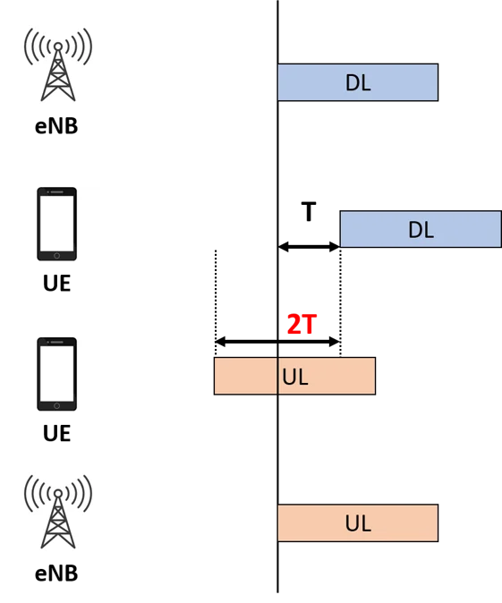
The Solution: Timing Advance (TA) The tower (eNB) measures exactly how “late” User B’s signal is. It then sends a command (TA Command) to User B saying: “Hey, you are far away. Please start transmitting slightly earlier than everyone else so your signal arrives at the same time as the others”.
- This command is generated in the MAC Layer of the tower.
- The value is a 6-bit number (0–63) sent to the phone.
