You built the Frame Structure. You know that LTE is a grid of time (10ms Frames 1ms Subframes Symbols) and frequency (Subcarriers).
A radio signal is 2-dimensional. It occupies time, but it also occupies Frequency (Vertical Axis). This is where OFDM (Orthogonal Frequency Division Multiplexing) comes in.
What is a Subcarrier? Imagine your LTE network has 20 MHz of bandwidth (like a wide highway).
- Old Technology (Single Carrier): We would treat that 20 MHz as one giant lane. If I send data, I occupy the entire 20 MHz for that millisecond. This is inefficient because if there is interference at a specific frequency spot, the whole signal dies.
- LTE Technology (OFDM): We slice that 20 MHz highway into 1,200 tiny, narrow lanes.
- Each “tiny lane” is called a Subcarrier.
- The width of one subcarrier is exactly 15 kHz.
Note
A Subcarrier is the smallest unit of Frequency in LTE.
What is OFDM? (The “Grid Maker”) OFDM is the technology that stacks these 1,200 subcarriers on top of each other without them crashing.
- “Orthogonal” means “Perpendicular” or “Non-interfering.”
- Mathematically, the peak of Subcarrier 1 aligns exactly with the zero-crossing of Subcarrier 2.
- Result: We can pack these 1,200 subcarriers incredibly tight together (no wasted space between lanes).
The Problem: In Phase 1, the grid is empty. To send data, the Network (eNB) needs to communicate with the User (UE).
- “Hey UE, I have a YouTube video for you.” (Downlink Assignment)
- “Hey UE, upload your request now.” (Uplink Grant)
These commands are called DCI (Downlink Control Information). The problem is: How much space on the grid does a command take? The Subframe/Symbol is where the data lives. However, we cannot use them as a “Unit of Measurement” for one specific reason: Modulation.
The “Empty Box” Problem If I use QPSK, I put 2 small items (bits) in that box. If I use 64QAM, I pack 6 items (bits) in that same box. If an engineer says, “I sent 1 Symbol of data,” it is meaningless. Did they send 2 bits? Or 6 bits? This is why we cannot use “Symbol” as a data unit. It is a Time Unit only.
We cannot measure data in “milliseconds.” We need a unit that represents information capacity.
Section 2 defines this hierarchy of “Boxes”:
1. The Cargo (Modulation Schemes)
Before we define the containers (RE, REG, CCE), we must define the “cargo” that goes inside them. This is Modulation.
Modulation is the process of manipulating the radio wave (Phase and Amplitude) to represent binary bits (0s and 1s).
QPSK (Quadrature Phase Shift Keying)
- Concept: The network manipulates the wave into 4 distinct states (North, South, East, West).
- Capacity: Since there are 4 options (), each symbol carries 2 bits.
- The Trade-off: The “targets” are far apart. Even if there is noise (interference), the phone can easily distinguish “North” from “East.”
- Role in LTE: This is the standard for the Control Channel (PDCCH). Control commands must be robust. We don’t care about speed; we care about survival.
16QAM (Quadrature Amplitude Modulation)
- Concept: We manipulate Phase and Amplitude to create 16 distinct states.
- Capacity: 16 options () = 4 bits per symbol.
- The Trade-off: The targets are closer together. You need a decent signal to distinguish them.
64QAM
- Concept: 64 distinct states.
- Capacity: 64 options () = 6 bits per symbol.
- The Trade-off: The targets are tiny and packed together. Any noise will cause an error. Used only for high-speed user data (PDSCH) in excellent conditions.
Crucial Rule for Section 2:
For the rest of this explanation regarding Resource Allocation (Control Channel), assume we are using QPSK. The network prioritizes reliability over speed for control signals.
2. The Hierarchy of Units
Now that we know 1 Symbol = 2 bits (in QPSK), let’s build the hierarchy described in the ShareTechnote document. Level 1: The Atom — Resource Element (RE) This is the smallest physical unit in LTE.
- Dimensions: 1 Subcarrier (Freq) 1 Symbol (Time).
- Capacity: In QPSK, 1 RE holds 2 bits.
- Visual: Imagine a single pixel on your monitor.
Level 2: The Molecule — Resource Element Group (REG) Mapping data to single REs is inefficient for the hardware. The system prefers to process small “blocks.”
- Definition: 1 REG = 4 REs.
- The “Pilot” Complication: In the first few symbols of a subframe (where the Control Channel lives), the LTE tower blasts Reference Signals (RS). These are “Pilot” signals for the phone to measure signal strength.
- Rule: You cannot put control data on top of a Pilot.
- Result: An REG consists of 4 usable REs. It will “skip” over the Pilots to find 4 empty slots.
- Capacity:
Level 3: The Brick — Control Channel Element (CCE) An REG (8 bits) is too small to hold a command. A typical LTE command (DCI) is roughly 40 to 60 bits long. We need a standardized “container” that can hold one full command.
- Definition: 1 CCE = 9 REGs.
- The Math:
- Capacity (The “Why”):
- Logic: A 72-bit container is perfect. It can hold a ~50-bit command plus ~20 bits of error checking (CRC).
- Constraint: The CCE is the minimum currency. You cannot buy “half a CCE.” Even if your command is small, you must use 1 full CCE.
Reliability Strategy — Aggregation Levels
This is the most “intelligent” part of the MAC layer.
We have established that 1 CCE = 72 bits. However, radio conditions change. A user at the edge of the cell (Cell Edge User) has a terrible signal. If we send them 72 bits, they might only receive 50 correctly due to noise. The command fails.
To solve this, LTE uses Aggregation Levels. This allows the network to “link” multiple CCEs together to send one single command.
- Aggregation Level 1:
- Uses 1 CCE (36 REs).
- Coding Rate: High (We send the bits once).
- Target: Users with Excellent Signal.
- Aggregation Level 2:
- Uses 2 CCEs (72 REs).
- Coding Rate: Medium (We repeat the data/redundancy twice).
- Target: Users with Good Signal.
- Aggregation Level 4:
- Uses 4 CCEs (144 REs).
- Target: Users with Bad Signal.
- Aggregation Level 8:
- Uses 8 CCEs (288 REs).
- Coding Rate: Very Low (Massive redundancy).
- Target: Users with Terrible Signal.
Sending a command at Level 8 is very “expensive.” It uses up 8 CCEs of space just to talk to one user. The network tries to avoid this unless necessary.
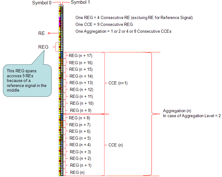
- Vertical Axis = Frequency: The vertical stack of small boxes (Resource Elements) represents different frequencies (subcarriers) being transmitted at the same time.
- The “Column” Concept:
- The Left Column represents all the data (on various frequencies) being sent during the time period of Symbol 0.
- The Right Column represents all the data being sent during the time period of Symbol 1.
The “stacking” you see in the image (subcarriers stacked on top of each other) is a property of OFDM (the modulation technique), not the Duplexing method (TDD vs FDD).
Since both FDD and TDD use OFDM for the Downlink, they both use the exact grid structure shown in your image.
The column represents a stream of these REs. The labels “Symbol 0” and “Symbol 1” at the top indicate that these REs are located within the first few symbols of a subframe, which is the dedicated region for control data.
When grouping REs into an REG, the system skips over any RE containing a Reference Signal. Therefore, while an REG always contains 4 usable data REs, it might physically occupy 5 slots in the grid if one of those slots is a Reference Signal.